Turn a staged interconnect into a phased compute plan.
Grid models the full power chain, from utility feed to rack, and converts the megawatts you can actually energize, phase by phase, into racks, GPUs and dates.
| Stage | 01 · Plan |
|---|---|
| Reads | Facility Graph |
| Upstream | Site systems (read-only) |
| Hands off to | Aidni Thermal |
| Primary output | Power envelope per phase (MW IT) |
Why this system exists
- 01
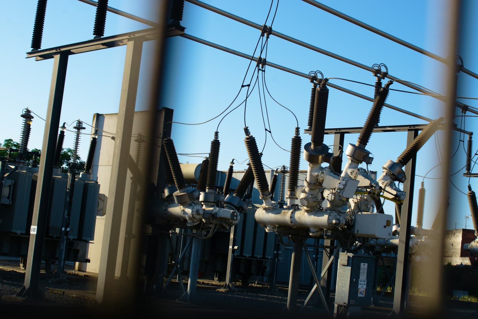
Power delivered to the site, not server efficiency, is what stops a build. Interconnects arrive in stages, and a campus designed for its final load sits partly dark for months.
- 02
Compute is the expensive part of the building. Hardware inside can exceed $30M per MW, roughly three times the shell, and accelerators age out on a 24–36 month cycle whether or not they are powered.
- 03
Most capacity plans live in spreadsheets disconnected from the one-line diagram, so headroom, redundancy and stranded capacity are guessed, not computed.
The mechanism, step by step.
Model the power chain
Utility service, substations, switchgear, UPS, PDUs and busway become typed nodes in the Facility Graph, each with rating, redundancy mode and phase.
Compute the envelope
For every energization phase Grid calculates usable IT load after PUE, redundancy and derating, and flags which components bind first.
Place the compute
Rack densities and GPU configurations are fitted into the envelope, row by row, producing a phased deployment plan with headroom shown in MW and in GPUs.
Price the delay
Every month of stranded capacity is valued against the compute it delays, so phasing decisions are made in dollars, not just megawatts.
What is a month of waiting for power worth?
Move the inputs to see how a utility allocation becomes racks and GPUs, and what each month of delay costs in accelerator life.
Simplified planning model: IT load = utility allocation ÷ PUE; ignores redundancy topology and derating, which a Site Assessment computes from your one-line diagram. Default capital per MW follows Brookfield's 2026 outlook (compute can exceed $30M/MW). Default useful life is an editable assumption reflecting a 24–36 month accelerator refresh cycle. Not an engineering design.
- Power envelope per phase (MW IT)
- Phased rack and GPU plan
- Binding-constraint register
- Stranded-capacity report with $ value
- EPMS / power monitoring
- Utility interconnection schedule
- One-line diagrams (PDF, DWG export)
- DCIM rack inventory
Power-first compute planning. Today, interconnection, rack layout and GPU procurement are planned in separate tools by separate teams. Grid plans compute directly against delivered megawatts, phase by phase, and prices every month of delay in lost accelerator life, so energization and procurement are sequenced as one decision.
Why this matters for the field →Bring us one site. We will show you its real capacity.
A six-week Site Assessment maps the power envelope, the cooling design and the compute plan for one facility, delivered by the engineers who build the platform.